Datasheets (Don't) Lie
The Circuitguy.com guide to reading datasheets.
"Datasheets Lie." I'm sure we've all said it before. I've said it myself, and I still catch myself saying it. Just because we say it, it doesn't mean it's true. Most datasheets are, in fact, very accurate and representative of the part. Sometimes you have to read all the lines to find the truth between the facts.
My expertise is in power electronics. As such, I tend to work with power semiconductors, mostly mosfets and IGBTs. Since mosfets are commonplace (and misunderstood) in both the hobbyist and professional realm, I will focus this guide on reading and interpreting mosfet datasheets.
The bulk of this article will focus on the IRFP4568 power mosfet. I am not associated with IRF in any way, shape, or form. I believe this part has a 'good' datasheet (my reasons will be explained throughout the article), but there is really nothing atypical or special about IRF, this datasheet, or the part it represents.
As a quick aside, when searching through an online vendor's inventory to pick a new part it's a good idea to check the manufacturer's page before finalizing your choice. Say I chose to write this article on the IRFP4321. At the time of writing digikey sells it in single unit quantities for $3.17 with no indication of any problems. IRF's website confirms that the part status is "Active & Preferred," which is good. However, the cross reference table recommends an upgrade to the IRFP4568 that this article is focusing on. Digikey is currently selling this part for $7.84. Pay careful attention to this at times. In this case, there's not necessarily any reason to choose the 4568 if the 4321 works in your application. Sometimes though, you will dig up an end-of-life product that may leave your design dependant on obsolete technology; not a good place to find yourself.
Initial Datasheet Impressions
OK, you may w ant to pull up the datasheet if you haven't already to follow along.
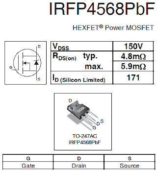
The first thing you will see is the 4568 is an N-Channel mosfet in a TO-247 package rated for 150V and 171 Amps. You will probably recognize the TO-247 as a high-powered through hole package, meaning this is a more serious power mosfet than most (perhaps if there's interest I'll write an article on package types). Typical applications aren't necessarily helpful. It does give you a warm fuzzy feeling if your particular application is listed though. In this case, it shows the mosfet is primarily focused on switching. If you plan to operate it in the linear mode (class A amplifier, electronic load, current limiter, current sink, etc.), you should evaluate the datasheet very very carefully.
The Tables
I'm going to breeze through the tables on the first and second pages fairly quickly. Most of the information here is fairly self-explanatory and simple. There are a few interesting things to point out though. First off, read the notes. In this datasheet they are marked by a circle with a number inside. These notes give conditions of the test or assumptions that are made. Taking data straight from the tables without reading the footnotes can usually get you into trouble.
The first thing that stands out is the reference to figures under the avalanche characteristics. This is a reasonably common practice, but sometimes numbers actually appear in this table.
Thermal Characteristics
If my "finding the truth between the facts" line was ever accurate it's in the thermal characteristics and power dissipation properties of power electronics devices.
The first thing you'll find on thermal characteristics is the little blurb in the table.
The flow of heat is usually modeled in electrical equivalents, with energy (wattage) being analogous to current, and temperature being equivalent to voltage. The thermal conductivity of materials is modeled with resistance and the thermal storage capacity is modeled by capacitance. From the table you can see that Rojc is 0.29 degrees C/W. This means for every watt the device is dissipating, the junction will be 0.29 degrees hotter than the case of the device.
The junction-ambient thermal resistance can be really misleading. In this case one of the notes says this is only when the device is soldered to a 1" square piece of copper PCB and refers you to app note #AN-994. This is really ironic since AN-994 specifically says it is not intended for through-hole parts and mentions the TO-247 package specifically. In this particular case, the TO-247 package is large enough compared to a 1" PCB that the real junction-ambient thermal resistance (free standing part) is very close to the cited 40 deg C/W. However, this is not normally the case, so be careful about relying on the theta JA rating to keep your free-standing part cool.
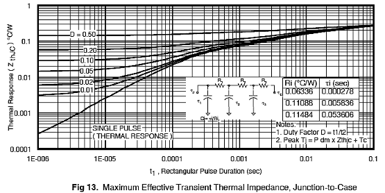
Now, this table-based thermal impedance metric is useful, but does not tell you the whole story of thermal characteristics.  Figure 13 from the datasheet tells you the complete story. The chart shows you the effective thermal resistance based on the duty cycle and frequency of a signal. This can be useful if you're really pushing the envelope. Note that this datasheet also provides a circuit within figure 13. This circuit includes electrical equivalents to thermal resistance and capacitance. The value of the thermal capacitors is J/C, similar to the electrical Q/V. So, completing the thermal model, Voltage is analogous to temperature in degrees C and current is analogous to power in watts. As a quick aside, heat sink manufacturers normally give you a thermal resistance for a given airflow, but they rarely give you the thermal capacity (aka thermal mass, thermal capacitance) of the heatsink. However, it's simply the specific heat of a material times it's mass. Aluminum's specific heat capacity is about 0.9 J/gC and copper is about 0.4J/gC. So a 100 gram aluminum heatsink would be modelled as a 90 J/C capacitor along with it's thermal resistance. If you feel you're really pushing the envelope on power dissipation it's a good idea to model these thermal characteristics. Note that this thermal equivalent circuit is one of the reasons I consider this a 'good' datasheet. If this is not available on the datasheet it's usually available from the manufacturer's website.
Safe Operating Area
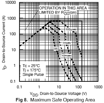
The final thing to pay attention to is the safe operating area. This is normally called the forward-biased safe operating area, FBSOA or just SOA. Failure to pay attention to this chart is the number one reason hobbyists and electrical engineers feel that datasheets lie.
The SOA takes into account not only thermal considerations (note: DO NOT rely only on the SOA chart for thermal considerations) but something that you can't find anywhere else in the datasheet. It is common knowledge that a mosfet, unlike a BJT, is a positive temperature coefficient device; which means that its resistance goes up as temperature rises which eliminates hot-spotting. Within the device, however, this is not 100% true. The SOA shows the time-current limit of the device. If this is not respected, the negative temperature coefficient of the junction will slowly lead to performance degradation and failure.

If the package is not capable of handling the full ratings you will normally see a 'limited by packaging' dotted line on this chart. In this particular case, the datasheet would lead you to believe the TO-247 package is capable of handling the full ratings of this part. This is one area this datasheet fails horribly. If you see something like this you should hunt around in other product offerings by the same manufacturer to find real limits. Sure enough, figure 9 in another IRF datasheet (IRFP3703) shows the package limit as 80 amps.
As a quick aside, the package current limit is not necessarily a hard and fast never-break rule. You should certainly keep the average current over thermally-significant time spans (a few seconds) below the limit though. It is not cited in the datasheets, but normally the limits are defined as the current that induces a 30 degrees C temperature rise in open air.
One of the first things to note is the 'DC' line. This mosfet is clearly not rated for linear operation. As I hinted previously in this guide, you should evaluate the datasheet carefully before using it in the linear region, and this particular figure should land the death blow to that hunt.
During hard switching, which is the typical use for a mosfet switch, the device must pass through the linear region. Remember that this is a 171 Amp, 150V part. So an engineer may look at this part and figure that it could safely switch 10 amps at 100V, which seems very very reasonable. However, looking at the safe operating area, this part is only rated for that condition for 100 uS. When the device first begins switching off, it is carrying the full current while the voltage across the device rises to 100V. If you are switching a highly-inductive load off, it would be prudent to ensure that the mosfet crosses the linear region within 100uS. This means that your mosfet driver should go from about 8.0V to about 2.0V within 100uS. These voltages were taken from figure 3, that shows the drain current vs. the gate voltage, and is roughly the linear region. If you run the calculations you will find that your mosfet driver needs to be capable of sinking about 8A to meet these conditions. Note that this method is very conservative, and assumes a worst-case inductive load, but these numbers are getting a little bad. If you find yourself in this situation you should simulate the circuit with your favorite Spice program.
Looking at the SOA curve it becomes fairly obvious that if you want to hard switch an 80A load, it would be prudent to do so only below about 30V (and run the thermal calculations!). Likewise, the hard-switched current should be kept closer to 1A in a 100V circuit. If you want to push the envelope further, you need some simulations and/or bench testing to back you up.
Conclusions
If you had only read the first page or two of this datasheet and (unsuccessfully) used this part, it would be easy to assume the datasheet lied to you. Unfortunately, you have to know and understand your application and carefully look through the datasheet to ensure that you're not violating anything.
There is enough information in the IRFP4568 datasheet alone to cover two or three articles like this. This article was meant to be a general overview of the most commonly-misunderstood aspects of datasheets. It is not a complete overview, but hopefully it will open your eyes or at least provide enough information to prevent you from damaging a part in the future. Good luck!
Original Publication Date:
2010-04-05
Last Updated:
2010-04-20
Additional Copyright Notice:
Most of the pictures in this document come from International Rectifier's IRFP4568 datasheet. They are not my property. I am not claiming to have authored them, created them, nor am I claiming any rights over them at all. I believe their use on this page complies with the fair use doctrine contained within US copyright law.
